

Grain temperature monitoring systems play an important role in maintaining grain quality and storage safety. These systems continuously monitor temperatures at different locations within stored grain and transmit the collected data to a central monitoring platform, helping operators detect abnormal temperature increases, potential hot spots, and other storage risks.
However, long-term exposure to humidity, dust, temperature fluctuations, mechanical stress, and rodent damage can affect the performance of temperature monitoring cables, sensors, data acquisition units, and communication equipment.
When a system experiences unstable temperature readings, missing sensor data, communication failures, or software errors, how can operators quickly identify the cause and restore normal operation?
This guide explains common faults in grain temperature monitoring systems, covering five key areas: sensors, signal transmission, data acquisition equipment, communication modules, and monitoring software. It also provides practical troubleshooting procedures and preventive maintenance recommendations for grain storage operators and maintenance technicians.
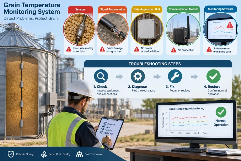
1. Abnormal Temperature Readings: Fluctuations, Inaccurate Values, or Missing Data
Temperature reading abnormalities are among the most common problems encountered in grain monitoring systems.
Before troubleshooting, determine whether the problem affects a single sensor, an entire temperature monitoring cable, or multiple storage bins.

1.1 Abnormal Readings from a Single Temperature Sensor
Common symptoms:
Temperature readings suddenly increase or decrease.
A sensor continuously displays the same temperature.
Temperature data is intermittently unavailable.
One monitoring point shows a significant temperature difference compared with nearby sensors.
Possible causes include sensor aging or failure, damaged internal cable conductors, loose connections, oxidized terminals, unstable power supply, and electromagnetic interference.
Troubleshooting procedures:
Review historical temperature records and compare the abnormal reading with neighboring monitoring points.
Use a portable temperature reader or an independent data acquisition device to test the suspected sensor.
Inspect cable connectors and terminals for looseness, corrosion, or moisture.
Check the monitoring cable for mechanical damage, rodent bites, or excessive tensile stress.
Repair or replace the faulty sensor or cable after confirming the cause.
An abnormal temperature reading does not necessarily indicate equipment failure.
A genuine hot spot inside stored grain may also produce an unusual temperature increase. If neighboring sensors show a similar rising trend, operators should investigate the actual grain conditions before concluding that a sensor is defective.
1.2 Temperature Displays 85°C, 125°C, or Other Unusual Values
Different temperature sensor technologies have different measurement characteristics and failure modes.
For example, the DS18B20 digital temperature sensor has specific startup behavior that must be considered during troubleshooting.
|
Temperature reading |
Possible cause |
Recommended inspection |
|---|---|---|
|
85°C |
Temperature conversion has not completed, unstable power supply, or actual temperature |
Check conversion procedures, supply voltage, and raw sensor data |
|
125°C |
Actual temperature near the upper measurement limit or abnormal data |
Verify raw data, data integrity, and actual temperature |
|
-50°C or other unusually low values |
Actual low temperature, data interpretation error, or sensor malfunction |
Compare with actual conditions and inspect raw readings |
|
No data |
Open circuit, short circuit, insufficient power, or poor connection |
Inspect wiring, power supply, and sensor response |
|
Frequent fluctuations |
Interference, unstable power, loose connections, or sensor failure |
Check electrical connections, supply voltage, and data integrity |
The DS18B20 temperature register contains an initial value corresponding to 85°C after power-up. This value is updated after a temperature conversion is completed.
Therefore, repeated 85°C readings may indicate that the sensor is being read before conversion has finished, or that power interruptions are repeatedly resetting the sensor.
For resistance-based sensors such as PT100, troubleshooting should instead follow the sensor's resistance-temperature characteristics and the specifications of its measurement circuit.
Important: A single temperature value should not be used as definitive evidence of an open circuit, short circuit, or sensor failure.
1.3 Multiple Sensors or an Entire Monitoring Cable Fail
When several sensors on the same cable simultaneously lose communication or display unstable readings, the problem may involve a shared electrical connection or data acquisition channel.
Common causes include:
Broken or short-circuited cable conductors.
Damaged junction boxes or cable connectors.
A faulty data acquisition channel.
Excessive cable length or sensor loading.
Insufficient power supply or excessive voltage drop.
Start by disconnecting the suspected cable or branch and observing whether the remaining sensors return to normal.
If the other sensors recover, the disconnected cable or branch may contain the fault.
For digital multipoint temperature monitoring cables, technicians should also verify that the sensor quantity, total cable length, power supply method, and communication timing comply with the equipment specifications.
2. Grain Temperature Data Acquisition Unit Failures
A temperature data acquisition unit collects readings from multiple sensors and transmits them to a monitoring platform.
When an acquisition unit fails, the problem may affect one monitoring channel, an entire grain bin, or multiple storage facilities connected to the same system.
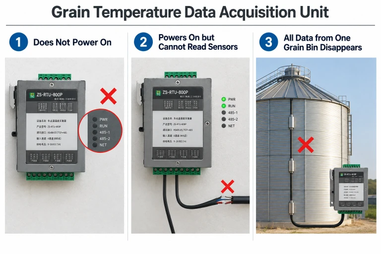
2.1 Data Acquisition Unit Does Not Power On
Common symptoms: The power indicator remains off, the equipment fails to start, or the device repeatedly restarts.
Possible causes include a damaged power supply, unstable input voltage, loose power terminals, blown fuses, or short circuits in connected equipment.
Troubleshooting procedures:
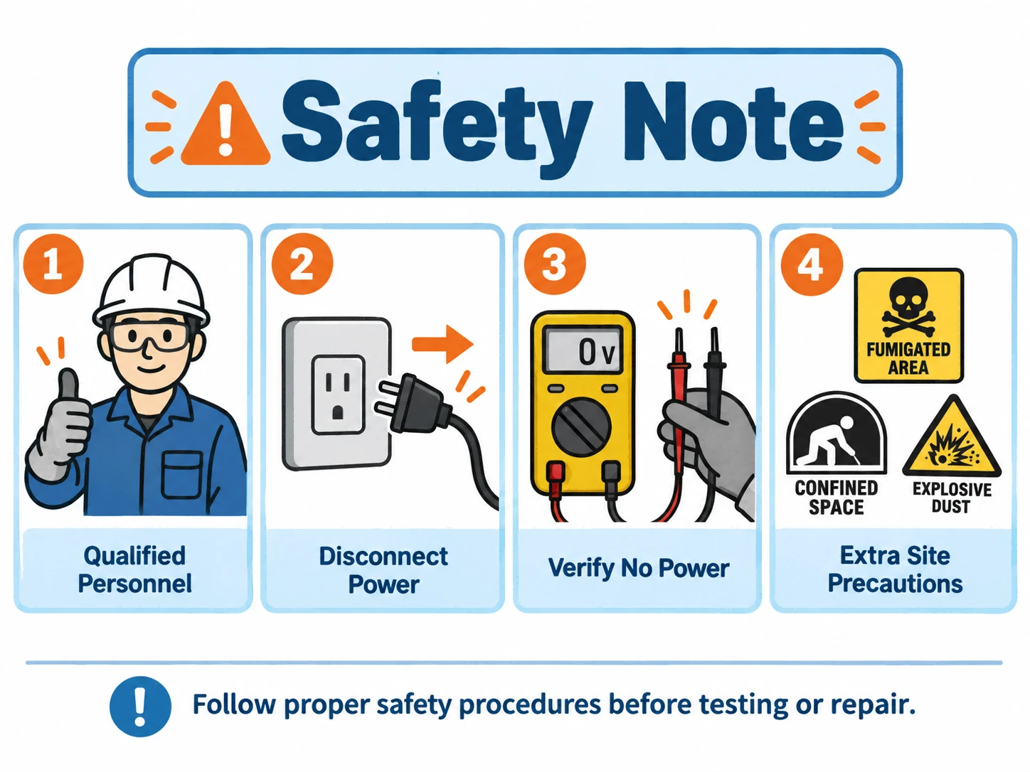
First, disconnect the power supply and inspect the power terminals and wiring.
After confirming that there is no short circuit, measure the input voltage according to the manufacturer's specifications.
Different data acquisition units have different power requirements. Technicians should not assume that every device operates at 5V or 12V.
For example, the ZS-RTU-800P multipoint temperature and humidity data acquisition unit supports a 9–36V DC power supply.
Always confirm the correct voltage range before testing or replacing a power supply.
2.2 Acquisition Unit Powers On but Cannot Read Sensors
If the acquisition unit starts normally but cannot collect temperature data, inspect the sensor-side connections.
First, verify that the monitoring cable is compatible with the acquisition unit and that the wiring matches the correct terminal definitions.
Next, check sensor power, signal connections, and acquisition channel settings.
A useful troubleshooting method is to connect a known working test cable containing a small number of sensors directly to the acquisition unit.
If the test cable works normally, the original monitoring cable or its connection may be responsible.
If the test cable also fails, investigate the acquisition channel, device configuration, and internal circuitry.
For multichannel acquisition units, a suspected cable can also be tested on another compatible, known working channel.
2.3 All Temperature Data from One Grain Bin Disappears
When every monitoring point inside a grain bin suddenly goes offline, first distinguish between a data acquisition problem and a data transmission problem.
For example, if the acquisition unit can still read temperatures locally but the monitoring computer displays no data, the problem may be located in the communication network rather than the temperature monitoring cables.
Local data verification should therefore be performed before replacing sensors or cables.
3. Communication Failures: No Response, Intermittent Connections, or Data Transmission Errors

Grain monitoring systems commonly use RS-485, Ethernet, or wireless networks to transmit temperature data.
Communication failures may cause devices to appear offline, produce timeout errors, or prevent temperature readings from reaching the monitoring platform.
3.1 RS-485 Communication Failure
RS-485 is widely used in industrial monitoring applications because it supports differential communication and relatively long transmission distances.
Common symptoms include a single acquisition unit failing to respond, multiple devices going offline simultaneously, intermittent communication, and repeated timeout errors.
|
Inspection item |
Troubleshooting method |
|---|---|
|
Device power supply |
Check the input voltage of the acquisition unit and communication module |
|
RS-485 wiring |
Verify A/B terminal definitions and wiring connections |
|
Device address |
Check for incorrect or duplicate communication addresses |
|
Serial communication parameters |
Verify baud rate, parity, data bits, and stop bits |
|
Communication cable |
Inspect for broken conductors, short circuits, and loose terminals |
|
Termination resistors |
Check termination according to the network topology |
|
Communication interface |
Test using a known working converter or compatible device |
For equipment using Modbus RTU, verify the slave address, function code, and register address.
RS-485 signal voltages depend on driver status, biasing circuits, termination, and other electrical conditions. A single fixed voltage range cannot reliably determine whether an RS-485 network is operating correctly.
Termination should also be selected according to the cable impedance and network configuration rather than applied indiscriminately.
3.2 Intermittent Communication
If communication succeeds occasionally but frequently fails during long-term operation, possible causes include electromagnetic interference, poor connections, and improper bus configuration.
Inspect whether communication cables run parallel to power cables connected to variable-frequency drives, motors, or other high-power equipment.
Where practical, separate communication cables from power cables according to the applicable electrical installation requirements.
Also inspect cable shielding, grounding, termination, and branch lengths.
In installations with significant ground potential differences, isolated RS-485 interfaces may help reduce common-mode interference and protect communication equipment.
3.3 Multiple Acquisition Units Lose Communication Simultaneously
When several acquisition units go offline at the same time, prioritize equipment and connections shared by those devices.
Potential fault locations include the main communication cable, RS-485 converter, network switch, and communication gateway.
Start at the monitoring computer and test the communication path section by section until the failure is located.
For wireless systems, inspect the communication module's power supply, network registration status, signal quality, and server connection.
4. Grain Monitoring Software Problems: Startup Failures, Missing Data, and Incorrect Readings
If the temperature monitoring cables and acquisition units operate normally but the monitoring platform still displays errors, the problem may be related to software or database configuration.
4.1 Monitoring Software Fails to Start
Possible causes include corrupted software files, operating system incompatibility, database service failures, licensing problems, and insufficient computer resources.
Start by reviewing the software error messages and system logs.
Check whether the required database service is running and whether its connection settings are correct.
If the software requires a license file or hardware security key, verify its authorization status.
When a fault appears immediately after a software update, investigate compatibility with the existing operating system, database, and communication drivers.
4.2 Incorrect Sensor Identification or Missing Historical Data
Sometimes the acquisition unit collects temperature data correctly, but the software displays readings under the wrong cable number or monitoring point.
This may indicate a sensor mapping or configuration problem.
Check the following:
Grain bin identification and temperature cable numbering.
Sensor IDs and monitoring point assignments.
Acquisition unit addresses and channel settings.
Communication protocol and register mapping.
Database records and historical data storage.
After replacing a temperature monitoring cable or sensor, ensure that the new sensor ID is correctly assigned to its intended monitoring location.
If real-time readings are normal but historical records are missing, investigate database write operations, storage capacity, time synchronization, and software service status.
4.3 Monitoring Platform Cannot Connect to the Server
For network-based systems, verify the acquisition unit's IP address, server address, communication port, and network connectivity.
For 4G-enabled devices, inspect the SIM card, mobile network connection, and communication module.
For MQTT-based monitoring platforms, verify the broker address, port, authentication settings, and data publishing status.
Distinguishing local data acquisition from remote transmission helps technicians determine whether the problem is on the equipment side or the software platform side.
5. Step-by-Step Troubleshooting Procedure for Grain Temperature Monitoring Systems
A systematic troubleshooting procedure helps technicians identify faulty components without unnecessary equipment replacement.
Grain Monitoring System Troubleshooting Workflow
1.Identify the scope of the problem
Determine whether the fault affects one sensor, one cable, one grain bin, or the entire system.
2.Check power and equipment status
Inspect power supplies, indicator lights, acquisition units, and device alarms.
3.Perform a local sensor reading test
Use a portable reader or independent acquisition device to confirm whether sensor data can be collected.
4.Inspect communication connections
Verify wiring, device addresses, communication parameters, and network connectivity.
5.Check software and data configuration
Review sensor mapping, protocol settings, database status, and server connections.
Repair, retest, and document
Sed ut perspiciatis unde omnis iste natus error sit voluptatem accusantium doloremque laudantium, totam rem aperiam, eaque ipsa quae ab illo inventore veritatis et quasi architecto beatae vitae.
6.FOUNDED COMPANY
Correct the identified fault, collect data over a suitable observation period, and record the maintenance results.
Three practical principles can improve troubleshooting efficiency: inspect shared equipment before individual branches, use non-destructive tests before disassembling components, and verify whether an unusual temperature represents a genuine grain condition before replacing sensors.
Known working sensors, cables, acquisition units, or communication modules can be used for substitution testing, provided they are electrically and functionally compatible.
6. Preventive Maintenance for Grain Temperature Monitoring Equipment
Preventive maintenance helps reduce unexpected system failures and improve the reliability of temperature monitoring data.
6.1 Protect Temperature Monitoring Cables
Regularly inspect temperature monitoring cables and protective conduits, paying particular attention to cable mounting points, grain loading and unloading areas, and cable connectors.
These locations may experience mechanical friction, grain movement, and repeated loading.
For cables permanently installed inside stored grain, select cable structures according to the storage facility's geometry, grain depth, and loading and unloading conditions.
Armored temperature monitoring cables and replaceable-core designs may simplify maintenance in applications where mechanical stress is significant.
6.2 Inspect Connections and Moisture Protection
Changes in humidity can cause terminal oxidation, increased contact resistance, and condensation inside electrical enclosures.
Inspect enclosure seals, cable glands, terminals, and waterproof connectors.
If moisture intrusion or corrosion is discovered, identify and correct the underlying cause before returning the equipment to service.
Do not assume that applying conductive grease is an appropriate repair for every electrical connection. Follow the terminal and equipment manufacturer's instructions.
6.3 Protect Equipment During Grain Fumigation
Grain fumigation may expose electronic equipment to corrosive chemicals.
Phosphine fumigants, particularly under conditions of elevated humidity and temperature, can contribute to corrosion of certain metals used in electrical equipment.
Before fumigation, coordinate with qualified fumigation personnel and follow the equipment manufacturer's recommendations for protecting, isolating, or removing sensitive electrical components.
After fumigation, personnel should enter affected areas only after the required ventilation, gas testing, and safety clearance procedures have been completed.
6.4 Conduct Regular Temperature Comparison Checks
Temperature monitoring cables should be inspected according to the equipment manufacturer's recommendations and the storage facility's maintenance procedures.
During empty-bin periods or scheduled maintenance, accessible sensors can be compared against a suitable reference thermometer.
If a monitoring point consistently differs from the reference measurement, investigate the sensor and its associated signal path.
For sensors that cannot be removed from stored grain, historical trends and neighboring sensor readings may provide useful diagnostic information. However, these comparisons are not equivalent to formal calibration.
6.5 Back Up Software Configurations and Historical Data
Maintenance should include both hardware and software.
Regularly back up monitoring software settings, equipment addresses, sensor IDs, monitoring point assignments, and historical temperature records.
Before replacing an acquisition unit, upgrading software, or changing a cable layout, save the existing configuration.
This can help prevent sensor identification errors and maintain continuity between historical and newly collected data.
7. Frequently Asked Questions (FAQ)
Q1: Does a temperature reading of 85°C mean that a grain temperature monitoring cable is broken?
Not necessarily.
For systems using DS18B20 sensors, 85°C may represent the sensor's initial temperature register value before a temperature conversion has completed.
Check the conversion process, power supply, communication response, and raw sensor data before concluding that the cable is broken.
Q2: What should I check if all sensors on one temperature monitoring cable stop responding?
Start by checking the shared signal wire, power supply, cable connectors, and acquisition channel.
Connect the cable to a compatible, known working acquisition device to determine whether the problem is associated with the cable or the original acquisition unit.
If disconnecting one branch restores communication with other sensors, inspect that branch for short circuits, leakage, or excessive bus loading.
Q3: Why is there no data on the monitoring computer when the acquisition unit is operating normally?
The problem may be located in the communication network or software configuration.
First, verify that the acquisition unit can collect sensor data locally.
If local acquisition works, inspect RS-485 communication, network connectivity, server status, and software settings.
Q4: How often should grain temperature monitoring cables be inspected?
Inspection frequency depends on the manufacturer's recommendations, the storage facility's maintenance procedures, and operating conditions.
Cable condition, connectors, temperature readings, and communication performance should be included in routine inspections.
More comprehensive checks can be performed during empty-bin periods or scheduled equipment maintenance.
8. Conclusion: Improving the Reliability of Grain Temperature Monitoring Systems
Faults in grain temperature monitoring systems can originate from sensors, temperature monitoring cables, data acquisition units, communication networks, or monitoring software.
Identifying the location of a fault is essential for selecting an appropriate repair method and avoiding unnecessary equipment replacement.
Routine maintenance should focus on cable protection, stable power supplies, reliable communication connections, and data integrity.
For new installations or system upgrades, temperature monitoring cables and data acquisition equipment should be selected according to grain bin structure, sensor quantity, cable length, and communication requirements.
Through proper installation, preventive maintenance, and systematic troubleshooting, grain storage operators can reduce unexpected system interruptions and maintain reliable temperature records to support safe grain storage.
Related Products and Further Reading
For additional information about grain temperature monitoring equipment, visit ZSTemperatureCable .
Explore multipoint temperature monitoring cables, armored cable solutions, and data acquisition equipment for grain silos, steel grain bins, and flat storage warehouses.